Tying the System Together
Last Edit November 1, 1996; July 20, 2001
Am2904
Figure 7-3 diagrams the interconnect required between the
Am2904 and an array of Am2903s. A similar interconnect is required
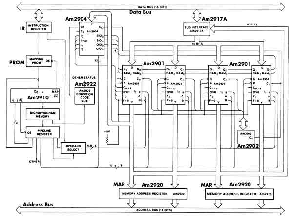
if the ALU is formed from Am2901s. Figure 7-4 presents the
block diagram of the CPU that has been under discussion. In includes
the IR (instruction register) connected between the system data
bus and the mapping PROM and also shows its connection to the A,B
address selectionMUX.
Figure 7-3 Full interconnection of Am2904-Am2903

Figure 7-4 Typical application of Am2904 with Am2901
The mapping PROM decodes the op code and supplies an address out
on tristate lines to the microprogram sequencer, an Am2910.
The Am2910 supplies the microprogram address to be fetched to the
microprogram memory and supplies, in this case, output enables to
the mapping PROM and the pipeline register. The Am2910 receives
- a 4-bit instruction out of the pipeline register
- an address into its Di inputs (the source of the address selected
by the decode of the instruction received)
- a condition code input on the CC' line
The CC' line is connected to a condition code MUX, an Am2922 in
this case, which is a registered MUX -- i.e., it latches the slection
code sent to it and therefore is not connected to a pipeline register.
It also has polarity control. The CC' line is attached to the CT
output of the Am2904.
The pipeline register is sufficiently wide to contain all of the
microinstruction fields in a horizontal format. In a typical system
this can vary between 32 and 128 bits. The HEX-29, a generalized
register architecture 16-bit CPU, has a 64-bit microword, with one
field with overlay. The SUPER-16, aslo a 16-bit system, but with
an instruction-fetch overlap and certain I/O features which allow
it to have a machine instruction execute time of 200ns, has a 96-bit
microword. [These systems existed in the 1970-1980s.]
The Am2904 is connected to the RALU status outputs and to the most
significant and least significant RAM and Q outputs. It is connected
to the system data bus so that the machine level status bits can
be read from or written into the status register.
The ALU consists of four Am2901 RALUs and an Am2902 carry-lookahead
chip. The DAi inputs are connected to the system data bus through
a bus interface and are connected to the MAR register. The MAR register
is connected to the system address bus. The A and B address lines
are sourced either from the IR, for register instructions, or from
the pipeline register, for implied register addressing, as selected
by the microinstruction via the operand select MUX.
Figure 7-5 shows the same architecture implemented using
the Am2903 RALU rather than the Am2901.
Figure 7-5 Typical application of Am2904 with Am2903

|

