Structured Design Methodology
Last Edit July 22, 2001
Fault grading
There are fault grading programs that score the vectors as to per-cent
faults covered. There are a number of fault-grading packages appearing
on the workstations and on mainframes.
Fault-grading is used to verify that the simulation bit vectors sufficiently
exercise nodes within the circuit to assure that the outgoing product
matches the customer specification.
If an array vendor does not support a particular package, it is likely
that the software will give misleading fault grade scores. Fault grade
scores depend on the modeling approach used as well as the vectors themselves.
Most fault-graders need a file or support program to reduce errors due
to global ground not switching, VCC, VSS or VDD not switching, or a terminated
output not switching and other, similar exceptions.
Insufficient fault coverage as determined in a fault grading analysis
may require the addition of vectors to the graded set.
Functional simulation vector fault-grading can be performed at AMCC using
the LASAR 6 simulator. AMCC looks for scores based on the interconnect
nets and not on the internal macro component interconnect links. MSI macro
modeling (and whether the macro is hard or soft) will affect fault grade
scores. AMCC recommends the creation of enough vectors to achieve a fault
coverage of 90% or higher.
| simulation stimuli and netlist |
----> fault-grader |
---> report grade |
At-speed simulation
In addition to function simulation, the designer must perform some at-speed
verification of circuit operation. One method is to perform a simulation
that is executed at the specified maximum frequency of operation of the
circuit with timing checks enabled.
At the minimum, these vectors should cover the critical performance paths
of the circuit and may cover the entire circuit.
The at-speed simulations are run using Front-Annotation. The Front-Annotation
results are not to be considered to be a specification of the final results.
The at-speed simulation is re-executed when Back-Annotation files are
available.
For conventionally specified array series, at-speed timing analysis is
done with the worst-case military or commercial (maximum) and with the
minimum library.
At-speed simulations are run with the print on change option for the
simulator (print_on_change, -c, list -change, etc.), monitoring the same
signals monitored by the functional simulation. Because these are complex
to evaluate, they are also performed in the sampled mode. They are run
using the maximum library and the minimum library.
Table 2-11 At-Speed Simulations
| minimum worst-case |
maximum worst-case |
|
sampled
|
print_on_change |
sampled |
print_on_change |
Timing Verifiers - An at-speed option
If they are supported by the array vendor, timing verifiers can be substituted
for at-speed simulation. Not all timing verifiers are supported by the
array vendors even if the corresponding simulators are supported. (The
Valid timing verifier is the only one currently supported by AMCC and
then only with certain libraries.) Check with the array vendor.
Verifiers can run min-max analysis against either the maximum or minimum
delay library. The min-max spread is the process, temperature, and voltage
variation for the library and is about 10-40%, as specified by the vendor.
This type of analysis can highlight spikes, ambiguity on clock paths,
and marginal timing performance.
Supported and non-supported EWS features
Timing verifiers emphasize the need to communicate clearly with the array
vendors. When evaluating an EWS or netlist purchase, consult the intended
array vendors for a list of systems and system features that the target
libraries support before committing to a design approach. The EWS system
may have software for which the vendor has not created models, rendering
that software useless without extensive further development.
There is a growing pool of independent workstation tool suppliers. For
these packages, the array vendor must also be consulted before assuming
that they can be used. Some of them alter the netlist that the vendor
may be using as input to the layout system, destroying the circuit interface.
Always refer to allowed equipment and EWS configuration supplied by the
target array vendors. Consult with them before starting a purchase or
a design.
Create the AC test simulation vectors - Optional
AC tests are optional and may be written to check either propagation
path delay in a non-memory path or external set-up and hold time for memory
elements. Both rising and falling edges should be checked.
AC test simulations may be concatenated into one simulation file provided
clear documentation of start and stop time addresses are provided. Each
test (one pair of input-output pads, one edge direction) must initialize
the circuit so that the test can be performed, provide the stimuli and
run until the effect of the stimuli is seen at the circuit output.
AC test simulations are run using the maximum and then the minimum library.
In each case, run once for sampled results and once for print on change.
AMCC performs only path propagation delay AC tests. For older AMCC arrays,
there is a limit of 20 tests over 10 paths, with bus lines handled as
multiple paths. AMCCVRC is used by AMCC customers to screen AC Test simulation
vectors.
Table 2-12 AC-Test Simulations
| minimum worst-case |
maximum worst-case |
|
sampled
|
print_on_change |
sampled |
print_on_change |
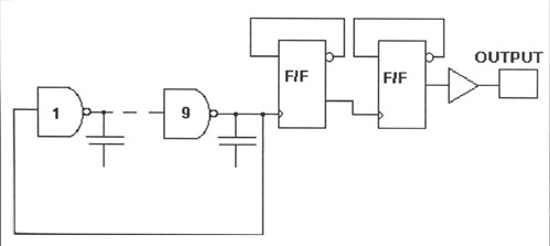
AC Speed Monitor
The AC speed monitor that AMCC built into the Q20000 Series base arrays
removes the requirement for customer-generated AC test simulation vectors.
This on-chip device will be added to all future arrays.
The basis of the AC monitor is a 9-stage ring oscillator followed by
a 2-stage divide by 4 counter. Each stage uses 100 mils of second and
third layer metal to evaluate metal loading. The accuracy of the counter
is 0.005% up to 100MHz.
The AC speed monitor uses two pads, a power supply pin and the output
pad, that are bonded out to external package pins. (See Figure 2-6.)
Figure 2-6 AC Speed Monitor - Q20000 Series Arrays
Parametric testing - Optional
Parametric testing for VIH, VIL is optional. There are several different
methods of setting up a parametric simulation. One approach is the use
of a parametric gate tree, where all circuit inputs (clocks and set and
reset included) are treed by NOR, AND or OR gates (SSI logic) to a single
output. The cost is the number of internal cells needed to implement the
gate tree, one output and an added load on the primary input signals.
The vectors are the minimal test sequence (100% fault coverage) for that
gate tree. A minimal sequence changes one input per vector and the output
toggles every vector. Every input is switched from 1-0 and from 0-1, one
by one.
The parametric vector set is combined with the functional simulation
vector set for fault-grading.
Parametric simulation is run once, using the maximum worst-case library
and a sampled output. The vendor may require that the minimum simulation
also be run. AMCCVRC can be run to check parametric testing simulations.
Table 2-13 Parametric Simulations
| minimum worst-case |
maximum worst-case |
| sampled |
sampled |
|
