Logic Design for Array-Based Circuits

by Donnamaie E. White

Copyright © 1996, 2001, 2002 Donnamaie E. White


Faults and Fault Detection

Last Edit July 22, 2001


2:1 MUX Example

Figure 9-14 shows a 2:1 MUX, its equation and its existence function. The minimal test sequence is shown in the darkened edges. The table shows the test vector (output listed first), what is tested, and what changes in each vector. Note that X3, the output, must always change, while only one input is allowed to change.

Figure 9-14 2:1 Mux Test Sequence Analysis
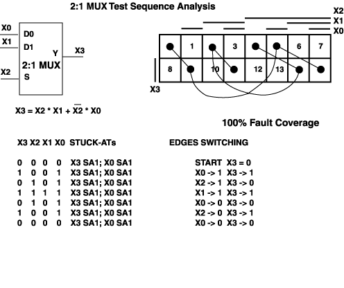
 

Figure 9-15 shows the same circuit, but this time lists both of the possible test sequences. In this case, the sequences are equal in length and coverage (100%).

Figure 9-15 Choosing A Sequence When Two Are Available


Copyright @ 2001, 2002 Donnamaie E. White, White Enterprises
For problems or questions on these pages, contact dew@Donnamaie.com


© 2024 Internet Business Systems, Inc.
670 Aberdeen Way, Milpitas, CA 95035
+1 (408) 882-6554 — Contact Us, or visit our other sites:
AECCafe - Architectural Design and Engineering TechJobsCafe - Technical Jobs and Resumes GISCafe - Geographical Information Services  MCADCafe - Mechanical Design and Engineering ShareCG - Share Computer Graphic (CG) Animation, 3D Art and 3D Models
  Privacy PolicyAdvertise