Faults and Fault Detection
Last Edit July 22, 2001
3:1 MUX Example
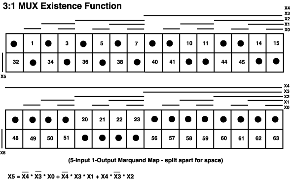
Figure 9-16 show the Existence Function for the 3:1 MUX. To keep
the map on one page, the Marquand map was broken into two halves. X5 is
the output and X0-X4 are the inputs (3 data inputs and 2 select inputs).
Figure 9-16 3:1 Mux Existence Function

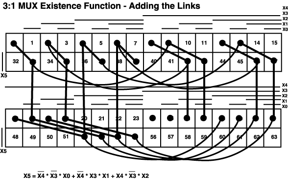
Figure 9-17 adds the logical-distance-1 edges. In each case, connect
the two points iff (if and only if) one input changes state and one output
changes state.
Figure 9-17 Adding The Links

Figure 9-18 shows one sequence in dark edges. This is for a non-clocked
circuit. The actual circuit simulated used a clock output, doubling the
size of the vector set (change data in one step, change the clock in the
next).
Figure 9-18 Identifying The Sequence

|